Sabado, Marso 10, 2012

Instantaneous and Average Power


           Power analysis is of paramount importance. Power is the most important quantity in electronic and communication systems because such systems involve transmission of power from one point to another.

                We will begin by defining instantaneous and average power.

There are several different definitions of power in AC circuits; all, however, have dimension of V*A or W (watts).


Instantaneous power:

  p(t) is the time function of the power,  p(t) = u(t)*i(t). It is the product of the time functions of the voltage and current. This definition of instantaneous power is valid for signals of any waveform. The unit for instantaneous power is VA.


Real or average power:  

P can be defined in two ways: as the real part of the complex power or as the simple average of the instantaneous power. The second definition is more general because with it we can define the instantaneous power for any signal waveform, not just for sinusoids. It is given explicitly in the following expression


The unit for real or average power  is watts (W), just as for power in DC circuits. Real power is dissipated as heat in resistances.
Instantaneous Power p(t) 


REACTIVE POWER


  We know that reactive loads such as inductors and capacitors 

dissipate zero power, yet the fact that they drop voltage and 

draw current gives the deceptive impression that they actually

 do dissipate power. This “phantom power” is called reactive power.

What is a reactive Power?

  Reactive power  (Q)     

-       is the imaginary part of the complex power. 
- it is given in units of  volt-amperes reactive (VAR). It is positive in an inductive circuit and negative in a capacitive circuit. This power is defined only for sinusoidal excitation. The reactive power doesn't do any useful work or heat and it is the power returned to the source  by the reactive components (inductors, capacitors) of the circuit. 


The mathematical symbol for reactive power is  the capital letter Q. The actual amount of power being used, or dissipated, in a circuit is called true power, and it is measured in watts (symbolized by the capital letter P, as always). The combination of reactive power and true power is called apparent power, and it is the product of a circuit's voltage and current, without reference to phase angle. Apparent power is measured in the unit of Volt-Amps (VA) and is symbolized by the capital letter S.


As a rule, true power is a function of a circuit's dissipative elements, usually resistances (R). Reactive power is a function of a circuit's reactance (X). Apparent power is a function of a circuit's total impedance (Z). Since we're dealing with scalar quantities for power calculation, any complex starting quantities such as voltage, current, and impedance must be represented by their polar magnitudes, not by real or imaginary rectangular components. For instance, if I'm calculating true power from current and resistance, I must use the polar magnitude for current, and not merely the “real” or “imaginary” portion of the current. If I'm calculating apparent power from voltage and impedance, both of these formerly complex quantities must be reduced to their polar magnitudes for the scalar arithmetic.
There are several power equations relating the three types of power to resistance, reactance, and impedance (all using scalar quantities):

Resistive load only:

True power, reactive power, and apparent power for a purely resistive load.
Reactive load only:

True power, reactive power, and apparent power for a purely reactive load.
Resistive/reactive load:

True power, reactive power, and apparent power for a resistive/reactive load.

These three types of power -- true, reactive, and apparent -- relate to one another in trigonometric form. We call this the power triangle: (Figure below).

Power triangle relating appearant power to true power and reactive power.
Using the laws of trigonometry, we can solve for the length of any side (amount of any type of power), given the lengths of the other two sides, or the length of one side and an angle.
  • Power dissipated by a load is referred to as true power. True power is symbolized by the letter P and is measured in the unit of Watts (W).
  • Power merely absorbed and returned in load due to its reactive properties is referred to as reactive power. Reactive power is symbolized by the letter Q and is measured in the unit of Volt-Amps-Reactive (VAR).
  • Total power in an AC circuit, both dissipated and absorbed/returned is referred to as apparent power. Apparent power is symbolized by the letter S and is measured in the unit of Volt-Amps (VA).
  • These three types of power are trigonometrically related to one another. In a right triangle, P = adjacent length, Q = opposite length, and S = hypotenuse length. The opposite angle is equal to the circuit's impedance (Z) phase angle.

http://www.tina.com/English/tina/course/29power/power

THREE PHASE CIRCUIT

Most of the electrical power generated in the world today is three-phase. Three-phase power was first conceived by Nikola Tesla. In the early days of electric power generation, Tesla not only led the battle  concerning whether the nation should be powered with low-voltage direct current or high-voltage alternating current, but he also proved that three-phase power was the most efficient way that electricity could be produced, transmitted, and consumed. 


What is a THREE PHASE CIRCUIT?

  It is a common method of alternating-current electric power generation, transmission, and distribution. It is a type of polyphase system and is the most common method used by grids worldwide to transfer power. It is also used to power large motors and other heavy loads.


Three-phase has properties that make it very desirable in electric power system:

  • The phase currents tend to cancel out one another, summing to zero in the case of a linear balanced load. This makes it possible to eliminate or reduce the size of the neutral conductor; all the phase conductors carry the same current and so can be the same size, for a balanced load.
  • Power transfer into a linear balanced load is constant, which helps to reduce generator and motor vibrations.
  • Three-phase systems can produce a magnetic field that rotates in a specified direction, which simplifies the design of electric motors.

          There are several reasons why three-phase power is superior to singlephase power. 


1. The horsepower rating of three-phase motors and the KVA (kilo-voltamp) rating of three-phase transformers is about 150% greater than for single-phase motors or transformers with a similar frame size. 

2. The power delivered by a single-phase system pulsates, The power falls to zero three times during each cycle. The power delivered by a three-phase circuit pulsates also, but it never falls to zero. In a three-phase system, the power delivered to the load is the same at any instant. This produces superior operating characteristics for three-phase motors.

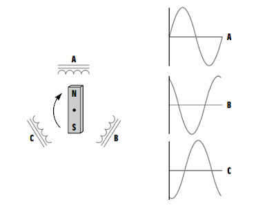
3. In a balanced three-phase system, the conductors need be only about 75% the size of conductors for a single-phase two-wire system of the same KVA rating. This helps offset the cost of supplying the third conductor required by three-phase systems.  A single-phase alternating voltage can be produced by rotating a magnetic field through the conductors of a stationary coil.


   The voltages  of three phase system are 120 out of phase with each other.  


If three separate coils are spaced 120° apart, three voltages 120° out of phase with each other will be produced when the magnetic field cuts through the coils. This is the manner in which a three-phase voltage is produced. There are two basic three-phase connections, the wye or star connection and the delta connection. 


WYE CONNECTION


 DELTA CONNECTION: 


Power Factor


One of the topics  in our CIRCUITS 2 subject was about POWER FACTOR.


What is a POWER FACTOR?

  The power factor of an AC electric power system is defined as the ratio of the real power flowing to the load to the apparent power in the circuit,and is a dimensionless number between 0 and 1.    

  where:

      Real power  -is the capacity of the circuit for performing work in a particular time.

     Apparent power - is the product of the current and voltage of the circuit. 


        Due to energy stored in the load and returned to the source, or due to a non-linear load that distorts the wave shape of the current drawn from the source, the apparent power will be greater than the real power.

         In an electric power system, a load with a low power factor draws more current than a load with a high power factor for the same amount of useful power transferred. The higher currents increase the energy lost in the distribution system, and require larger wires and other equipment. Because of the costs of larger equipment and wasted energy, electrical utilities will usually charge a higher cost to industrial or commercial customers where there is a low power factor.
       
For a DC circuit the power is P=VI, and this relationship also holds for the instantaneous power in an AC circuit. However, the average power in an AC circuit expressed in terms of the rms voltage and current is


where Ã¸   is the phase angle between the voltage and current. The additional term is called the power factor.


WHY IS POWER FACTOR IMPORTANT?

A power factor of one or "unity power factor" is the goal of any electric utility company since if the power factor is less than one, they have to supply more current to the user for a given amount of power use. In so doing, they incur more line losses. They also must have larger capacity equipment in place than would be otherwise necessary. As a result, an industrial facility will be charged a penalty if its power factor is much different from 1.

Industrial facilities tend to have a "lagging power factor", where the current lags the voltage (like an inductor). This is primarily the result of having a lot of electric induction motors  the windings of motors act as inductors as seen by the power supply. Capacitors have the opposite effect and can compensate for the inductive motor windings. Some industrial sites will have large banks of capacitors strictly for the purpose of correcting the power factor back toward one to save on utility company charges.

Biyernes, Marso 9, 2012

Sinusoids and Phasors


Historically, dc sources were the main means of providing electric power up until late 1800's. at the end of the century, the battle between direct current and alternating current began.


         Nicolas Tesla and George Westinghouse 
helped establish alternating current as the primary mode of electricity transmission and distribution.

           AC systems is more efficient and more economical  to transmit over long distances. To begin the analysis of AC systems, we should begin about to learn about SINUSOIDS AND PHASORS.


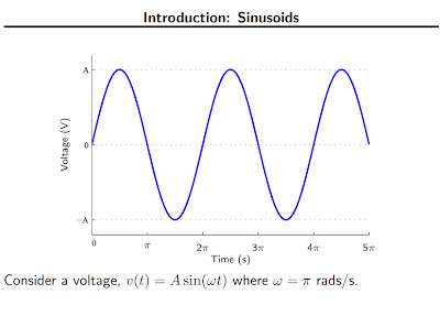
A SINUSOID is a signal that has the form of sine or cosine function. IT is usually referred to as alternating current.


http://web.cecs.pdx.edu/~prasads/Phasors.pdf

Sabado, Marso 3, 2012

Full Adder


At the very least, most people expect computers to do some kind of arithmetic computation, and thus, most people expect computers to add.
We're going to construct combinational logic circuits that perform binary addition. The first question you should ask when adding binary numbers, given all the time we've spent talking about representation is "what representation are we talking about"?
Clearly the choice of representation is going to affect how we perform the addition. Certain representations allow us to add in the way we add base ten numbers.


What is a Full Adder?
A Full Adder  is a combinational circuit that performs the arithmetic sum of three input bits. It consists of three inputs and two outputs. Three of the input variables can be defined as A, B, Cin and the two output variables can be defined as S, Cout. The two input variables that we defined earlier A and B represents the two significant bits to be added. The third input Cin represents the carry bit. We have to use two digits because the arithmetic sum of the three binary digits needs two digits. The two outputs represents S for sum and Cout for carry.

For designing a full adder circuit, two half adder circuits and an OR gate is required. It is the simplest way to design a full adder circuit. For this two XOR gates, two AND gates, one OR gate is required. 


Full Adders

The logic table for a full adder is slightly more complicated 


than the tables we have used before, because now we have 


3 input bits. It looks like this:


One-bit Full Adder with Carry-In and Carry-Out
CIABQCO
00000
00110
01010
01101
10010
10101
11001
11111


There are many different ways that you might implement this table. I am going to present one method here that has the benefit of being easy to understand. If you look at the Q bit, you can see that the top 4 bits are behaving like an XOR gate with respect to A and B, while the bottom 4 bits are behaving like an XNOR gate with respect to A and B. Similarly, the top 4 bits of CO are behaving like an AND gate with respect to A and B, and the bottom 4 bits behave like an OR gate. Taking those facts, the following circuit implements a full adder:


This definitely is not the most efficient way to implement a full adder, but it is extremely easy to understand and trace through the logic using this method. If you are so inclined, see what you can do to implement this logic with fewer gates.

Now we have a piece of functionality called a "full adder." What a computer engineer then does is "black-box" it so that he or she can stop worrying about the details of the component. A black box for a full adder would look like this:


With that black box, it is now easy to draw a 4-bit full adder:


In this diagram the carry-out from each bit feeds directly into the carry-in of the next bit over. A 0 is hard-wired into the initial carry-in bit. If you input two 4-bit numbers on the A and B lines, you will get the 4-bit sum out on the Q lines, plus 1 additional bit for the final carry-out. You can see that this chain can extend as far as you like, through 8, 16 or 32 bits if desired.

The 4-bit adder we just created is called a ripple-carry adder. It gets that name because the carry bits "ripple" from one adder to the next. This implementation has the advantage of simplicity but the disadvantage of speed problems. In a real circuit, gates take time to switch states (the time is on the order of nanoseconds, but in high-speed computers nanoseconds matter). So 32-bit or 64-bit ripple-carry adders might take 100 to 200 nanoseconds to settle into their final sum because of carry ripple. For this reason, engineers have created more advanced adders called carry-lookahead adders. The number of gates required to implement carry-lookahead is large, but the settling time for the adder is much better.http://computer.howstuffworks.com/boolean3.htm


Building Blocks: Full Adders


The problem with a half-adder is that there it doesn't handle carries. When you look at the left column of the addition

     1  0
     1  1  0
  +  0  1  1 
  -----------
 (1) 0  0  1
you see that you add three bits. Half adders only add two bits.
We need a circuit that can add three bits. That circuit is called a full adder.
Here are the characteristics of a full adder.
  • Data inputs: 3 (call them x, y, and cin, for carry in)
  • Outputs: 2 (call them s, for sum, and cout, for carry out)
Notice we now need to make a distinction whether the carry is an input (cin) or an output (cout). Carry in's in column i are due to carry outs from column i - 1 (assuming we number columns right to left, starting at column 0 at the least significant bit).
Here's a truth table for full adders.


Rowxycincouts
000000
100101
201001
301110
410001
510110
611010
711111


Ripple Carry Adders

Once you have half adders and full adders, you can now construct ripple carry adders.
A ripple carry adder allows you to add two k-bit numbers. We use the half adders and full adders and add them a column at a time.
Let's put the adder together one step at a time.

Before Adding


Adding Column 0

We add x0 to y0, to produce z0.


Adding Column 1

In column 1, We add x1 to y1 and c1 and, to produce z1, and c2, where ci is the carry-in for column i and ci + 1 is the carry-out of column i.


Adding Column 2

In column 2, We add x2 to y2 and c2 and, to produce z2, and c3.


Using Only Full Adders

We don't really need to use the half adder. We could replace the half adder with a full adder, with a hardwired 0 for the carry in.


Delay


SPINNING DISK

Design a disk spinning animation circuit for a CD player. The input to the circuit will be a 3-bit binary number A1A2A3 provided by another circuit. It will count from 0 to 1 in binary and it will repeat. the animation will appear on the top of the four lights of the LED display of the figure going clockwise. the animation should consist of a blank spot on a disk spinning around once, the the entire disk should blink on and off twice.


this is how it looks:


Where:


this is now its truth table:


Derive a K Map out of this truth table


From the equation formed, you can now create its Schematic Diagram: